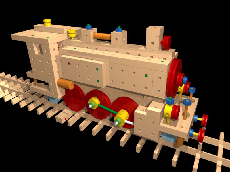
In this post we want to apply what we’ve learned earlier using the cage model:
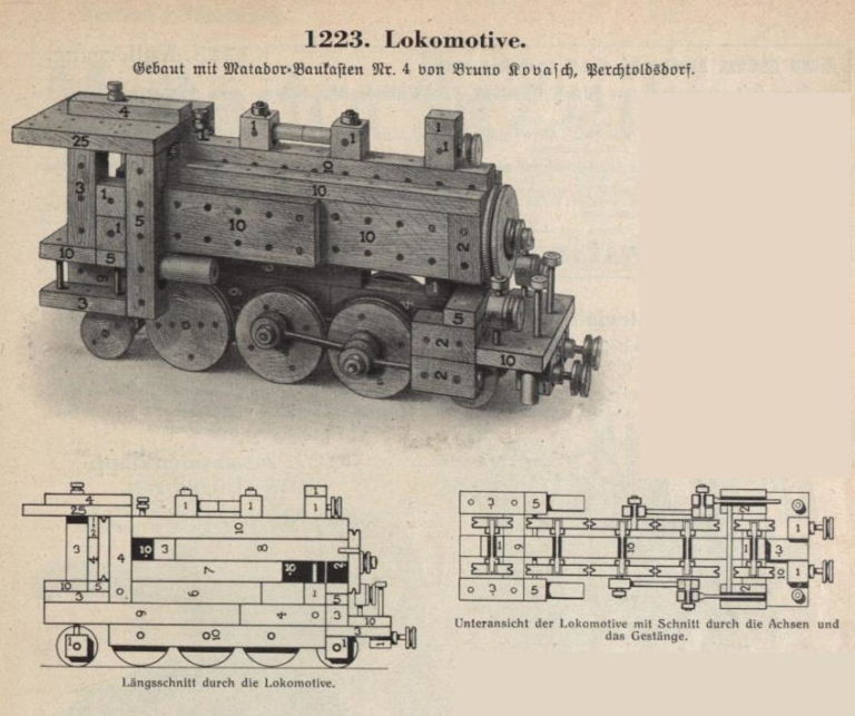
It’s going to be a steam locomotive! I purposely chose a model that isn’t built that often. (In fact, I’ve never seen a Matador model 1223, so if anyone has built it, please post.)
It is a model designed by the Austrian Bruno Kovasch from Perchtoldsdorf (near Vienna, Austria), around 1930:
Chassis:
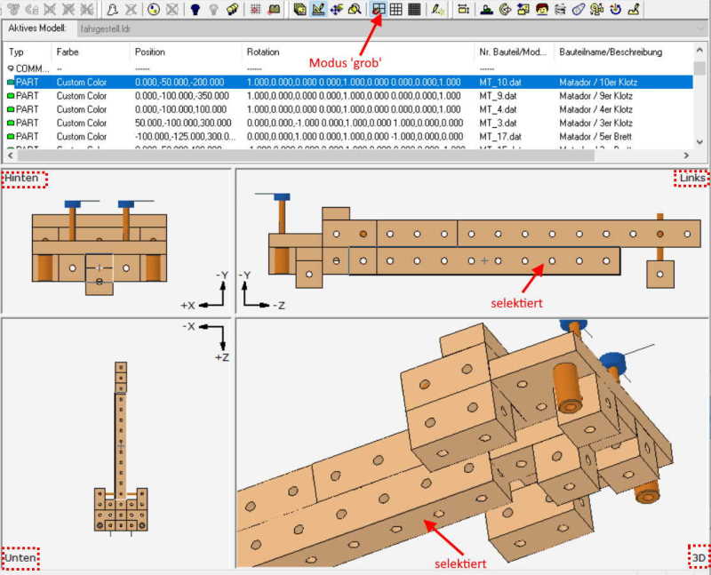
The construction is easy. As previously described for the cage model, we switch MLCad to ‘rough’ mode and drag all the required blocks into their positions.
After a short time we have the following picture in front of us:
As with any digital model we first (!) think about how to divide the object into assembly groups. This makes everything easier. We can check the groups for errors more easily and the animation also becomes much more straightforward.
The following grouping is recommended:
- Chassis (combined with wheel groups)
- driver’s cabin
- boiler group
- Wheel group (2, 3)
- headlamps
- connecting rods (two different)
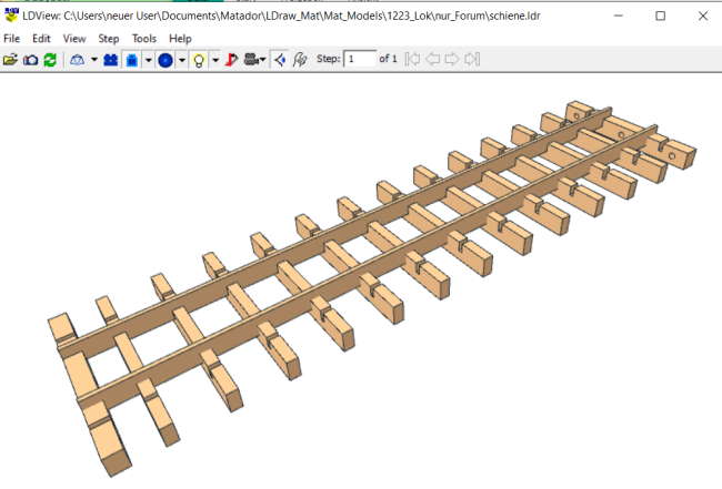
- Rails group (it should stand or move somewhere)
In contrast to the real Matador, we only have to build the wheel sets once because of the use of assemblies: Once for the wheel-3 axles , once for wheel-2 axles.
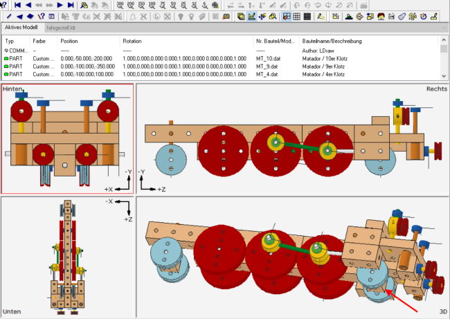
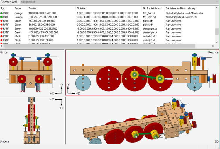
(Image on the left:) Notice how using the 3D view allows us to better identify critical visibilities. (The partially covered block-10 was selected in MLCad in the image.)
We now turn our attention to the wheel sets.
Each of these consist of only 5 parts. We make them ‘symmetrical’ in the coordinate system. The meaning of this we can see in the picture on the right:
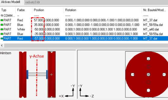
Arranging parts like this makes things clearer, even if the animation will only be added later.
Please note that the engine has the ‘smaller’ Matador rail gauge, meaning 35mm. The LDU spacing should therefore be 3.5 cm = 25 x 3.5 = 87.5 LDU units.
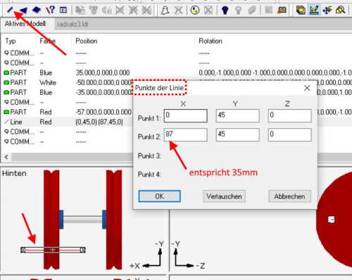
In cases where we would like to check our drawing with a measurement, I use the MLCad ‘Line’ command (in the following picture at the top left, arrow). If the data is entered as coordinates, we can see if the track width is correct. The lines can then be temporarily moved around in the image like rulers in order to measure distances directly in the model. A big advantage. –
We can delete them any time later. But even if not, they will only be displayed in LDView, not in POV-Ray rendering.
The wheel group ‘for the wheel-2 assembly we create the same way.
Final assembly of the chassis: We load the wheel-3 group three times into the chassis, then two times the wheel-2 group and move them into place.
Finally we create the small groups ‘headlamp’ and ‘buffer’. They are loaded twice into the chassis group.
Finally we create connecting rods, named ‘p1’ and ‘p2’ and position them to the wheels. It’s comparable difficult to do this on one side of the model. Therefore it is best to set the grid spacing in MLCad to ‘fine’ and then adjust the two connecting rods so that they ‘fit’. (See the animation chapter for more details.)
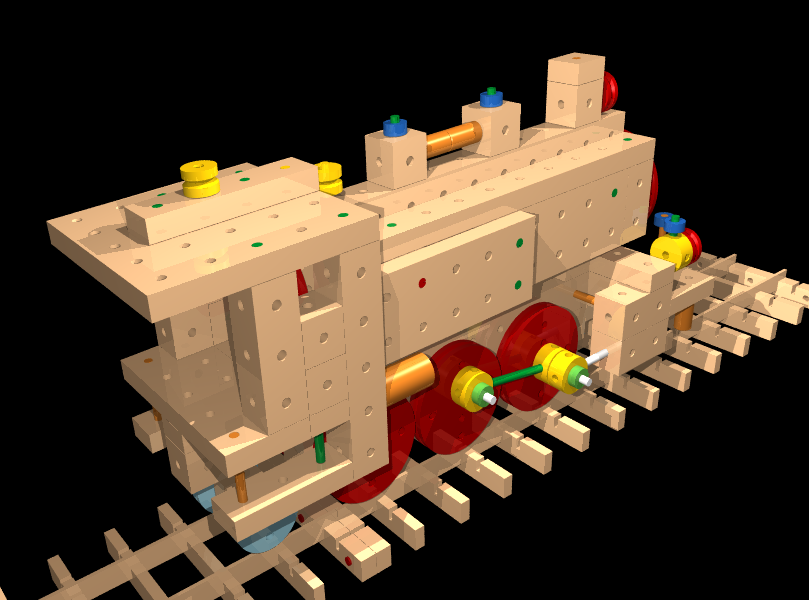
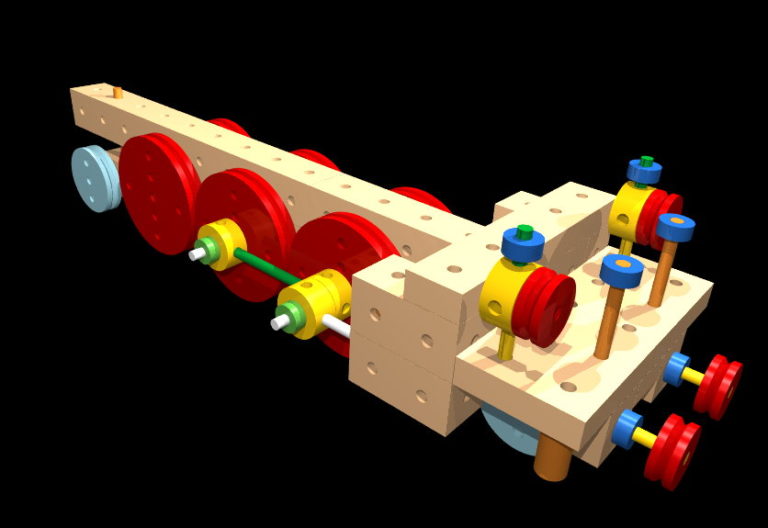
If we have placed everything correctly, the chassis should be finished and look something like this:
If you haven’t made it until here – all assembly groups of the chassis can be downloaded as LDR files.
The model should be viewable with LDView and can be rendered in POV-Ray.
Note: The files are extremely small, uncompressed less than
4kB (!). –
Here is the POV-Ray file, in case you haven’t installed the L3P app yet. With the POV file in place, rendering can be tested now.
Downloads:
fahrgestell_1223
fahrgestell_pov
(A quick render with POV-Ray produces the image on top.)